
Ames 7010097 (WATTS 0888820 & AMES 7010103) - 2 1/2 - ames 2000ss
It is important to note that when the valve is weeping or dripping, the cause is usually excessive pressure. Many times this is caused by thermal expansion. A T&P relief valve is not designed to nor should it be used to continuously control thermal expansion within a closed system. Thermal expansion of hot water within a closed system should be controlled with the installation of an approved expansion tank or by other means permitted by local code.
DCDABackflow
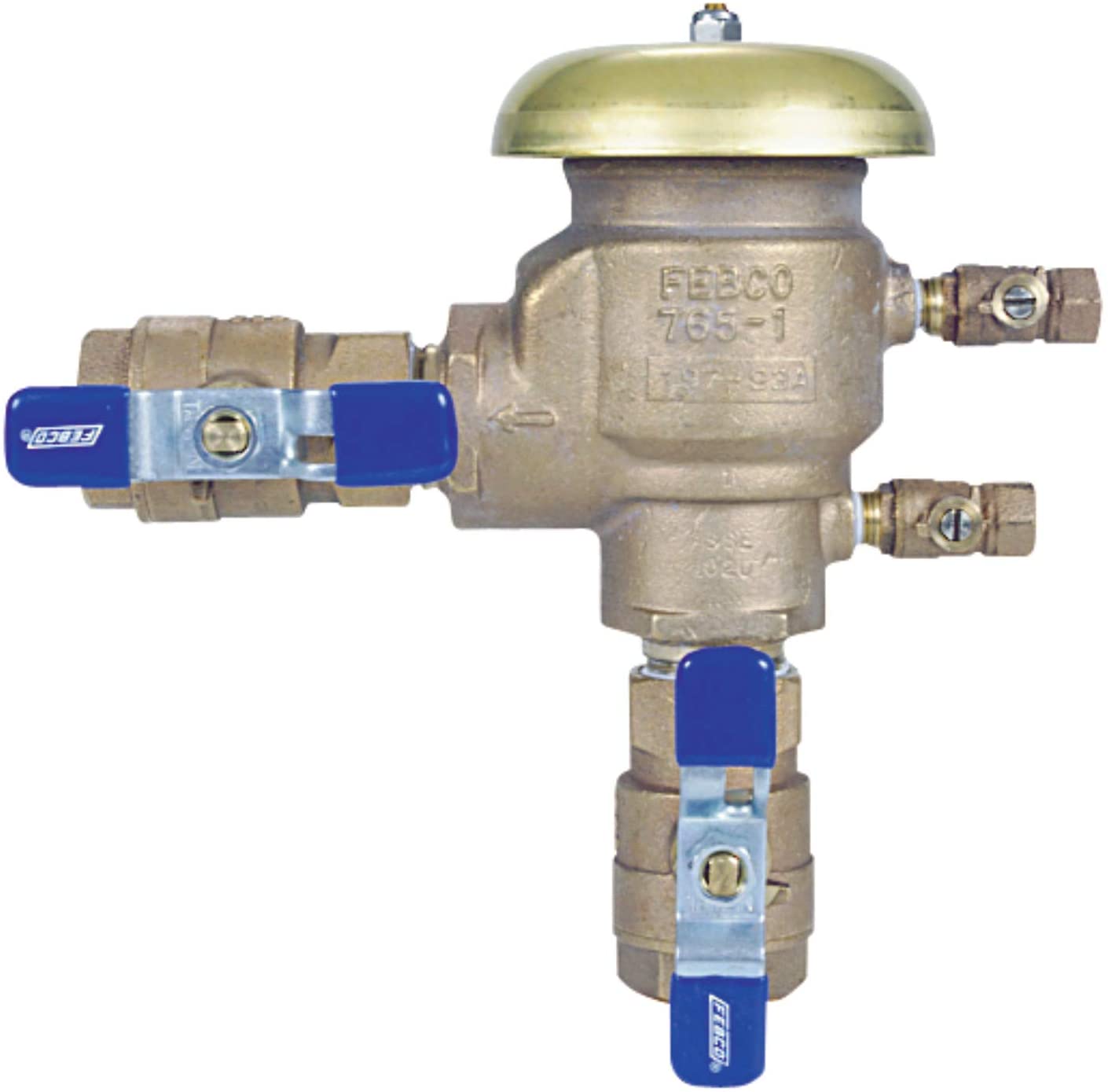
The PVB, or pressure vacuum breaker backflow assembly, is a limited use backflow assembly. Most commonly, they are found on residential irrigation systems, but even then, they are restricted as to if they can be installed.
Most common applications: Domestic Water Service - Commercial Properties Irrigation Systems - Residential and Commercial Fire Suppression Systems - Glycol/Chemicals Added Boiler Makeup Water Supplies Chiller Water Supplies Soda Machines (Stainless Steel Models Only)
The PVB has several installation restrictions. The first is a height restriction. The assembly must be a minimum 12 inches above the highest fixture in a system. It must also be a minimum 6" above grade and a maximum of 60" above grade. This means that a maximum of 4 feet of incline can occur between the backflow assembly and the highest fixture it will be protecting again.
Because of the limited use of double check valve assemblies, some water purveyors have eliminated them from their cross-connection control policy; meaning that while they are approved backflow prevention assemblies, they cannot be installed.
Most common applications: Fire Suppression Systems - No Anti-freeze, foam or chemicals Some commercial domestic water containment
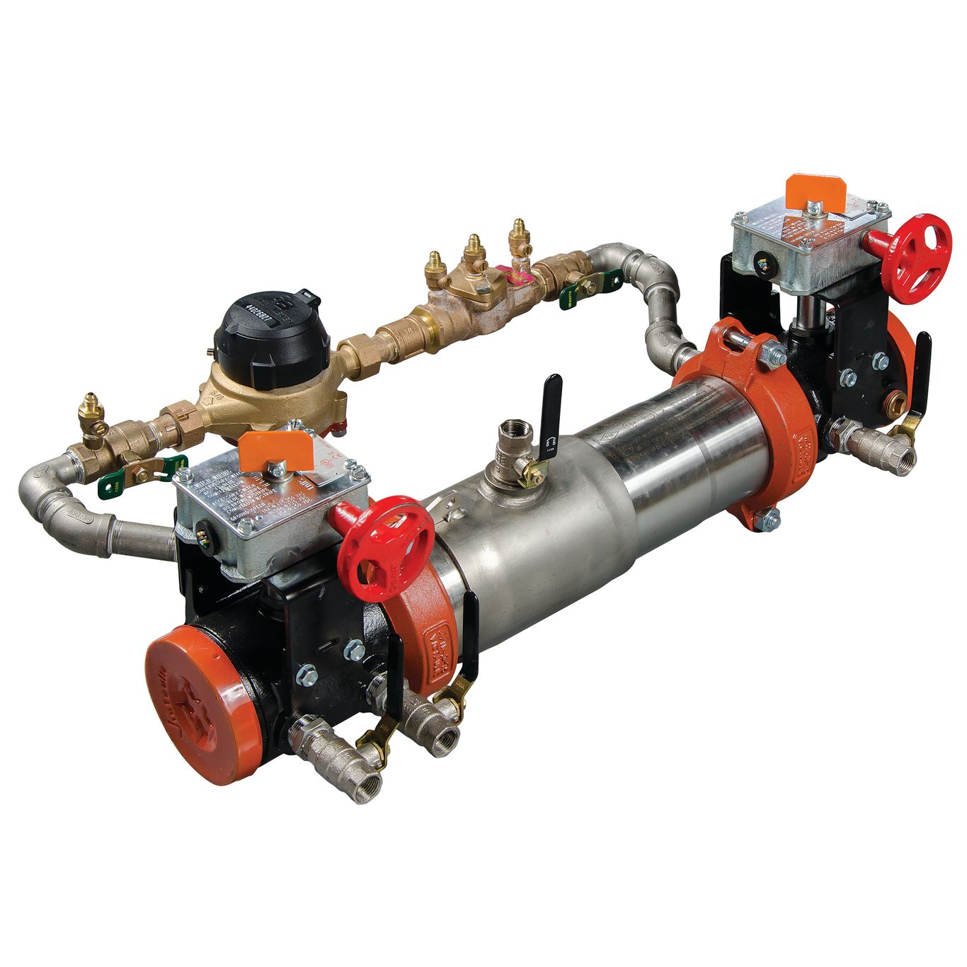
The RPDA and RPDA-II, RP detector assembly and RP Type II detector assembly (respectively), and the DCDA and DCDA-II, DC detector assembly and DC Type II detector assembly (respectively), are variations of the RP's and DC's. The standard detector assemblies have primary assemblies and then have low flow bypasses with additional backflow assemblies. The Type II detector assembly is reduced down to just a low flow bypass and a single check in parallel to the #2 check valve of the primary assembly. In all cases, the bypass has a meter installed on it to detect unauthorized use of the downstream water.
If you find yourself in a position that a detector assembly is required to be installed, be sure to speak with your water purveyor to see if they allow both Type I and Type II detector assemblies. A Type II may be cheaper upfront and down the road because maintainance is reduced.
The RP, or reduced pressure principle backflow assembly, it the most common type of assembly installed on domestic and irrigation systems. It is essentially two check valves with and intermediate differential pressure relief valve. They are designed to release water under certain situations and drainage is required for such discharge.
SVB's are limited in use in the same way that PVB's are. Must be 12" higher than the highest fixture being served and cannot be subjected to backpressure.
RPZbackflow
By in large, the RP is the most versatile type of backflow prevention and because of that, many water purveyors have adopted "RP Only" requirements for their cross-connection control problem. This is a double edged sword because it has the highest protection rating (outside of an air gap), but it is also the most expensive to install. Some installations will have to have systems installed to collect and pump out the water being discharged from the relief valve.
Dripping may continue because of debris within the valve, such as a build-up of calcium in the seat, and over time, large mineral deposits can make the valve ineffective. When a valve is discharging a large quantity of water, the cause is almost always excessive temperature.
The other restriction regarding the installation of a pressure vacuum breaker is that they cannot be subject to backpressure, which is one of the types of backflow. Backpressure happens when the demand pressure becomes higher than the supply pressure. This is most common due to elevation differences, pumps, thermal exansions, etc.
Because of the limitations on where and when they can be installed, many water purveyors have discontinued the use of PVB's within their jurisdiction. In some case, they may have grandfathered in existing PVB's but upon replacement, they must be converted to RP's.
The relieving capacity of the valve’s ASME/NB rating is established by Section IV, Part HG of the “ASME Boiler and Pressure Vessel Code.” The code reads, “Capacity certification tests of safety relief valves for water heating and hot-water supply boilers shall be conducted at 110% of the pressure for which the valve is set to operate.” So the capacity of a T&P relief valve set at 150 psi is based on its vessel pressurized to 165 psi.
If permitted by the local adopted code, AMSE/NB relieving capacities should only be considered for ASME vessels. The more restrictive CSA relieving capacities are always the safer choice.
While the 2012 National Standard Plumbing Code makes no distinction between the use of the ASME/NB and CSA capacity ratings, the 2015 NSPC will limit the use of the ASME/NB relieving capacity ratings to ASME vessels only.
The ASME/NB relieving capacity rating is more lenient than the CSA rating. The CSA rating is based on 15 psi of steam pressure, so the CSA rating will always be lower and, therefore, more stringent than the ASME/NB rating. ASME HLW water heaters are built to a more stringent code of construction than ANSI Z21 water heaters. The use of a valve’s ASME/NB capacity rating to protect an ANSI-built vessel could present a potentially dangerous condition.
As the name indicates, T&P relief valves are designed to protect water heaters and hot-water storage vessels against excess temperature and excess pressure. Most valves are rated at 150 psi and 210° F, but their capacity ratings vary greatly. Sometimes, an additional T&P relief valve with a lower temperature and pressure rating (typically 180° and 100 psi) is installed in a plastic hot-water distribution system to protect the piping system itself. A T&P relief valve is, in essence, a dual device because it meets the code requirements of an individual temperature relief valve and an individual pressure relief valve.
The pressure function of the valve also is controlled by the spring, disc and seat. When the pressure exceeds the valve’s pressure rating, the water pressure overcomes the spring. The spring is compressed (just like a typical pressure-only relief valve) and the water escapes between the disc and seat.
Environments that may require an SVB are labs, dialysis machines, manufacturing, etc. In fact, the misters spraying the fruit and veggies in the produce sections more than likely have backflow protection in the form of an SVB.
Pressure Reducing Valve
Typically, these are only installed on systems that are permanently in a static pressure state; meaning water is not supposed to be regularly flowing through the system. Easiest example is a fire suppression system. If no water is flowing, it means there is no fire and everyone is safe.
Backflows
The temperature function of the valve is controlled by an internal thermostatic element. At 210°, the internal expansion within the probe causes a piston to push against the valve’s disk. The spring is overpowered and compressed, and the water escapes between the disc and seat. The extremely hot water within the tank is forced out under pressure as cold water replenishes the discharge. The cold water rushing into the vessel lowers the water temperature, and when the temperature drops back below 210°, the valve is reseated.
The SVB, or spill resistant pressure vacuum breaker, is another testable vacuum breaker but is designed for situations where the environment needs to stay dry. PVB's are designed to allow water to flush through the air inlet in the event of supply side pressure loss. SVB's work a little different.
The DC, or double check valve backflow assembly, are two testable check valves in series. A check valve allow fluids to flow in one direction only. The DC looks very similar to an RP except that it does not have a differential pressure relief valve. Because of the lack of relief valve, the DC is rated for non-health hazards only. This basically restricts them to fire suppression systems that do not have anti-freeze, foam or other chemicals introduced.

The only way to determine the maximum allowable working pressure of a vessel is to read the nameplate that is attached to it. The pressure on the valve’s tag must be compared to the pressure on the vessel’s nameplate. The pressure rating of the relief valve must be equal to or less than the MAWP of the vessel. Most water heaters have an MAWP of 150 psi; however, some are rated higher, typically 160 psi. Some storage vessels have a lower pressure rating; they are commonly rated 125 psi.
Detector assemblies are becoming increasingly popular among water districts because of the meter tracking. Type I detector assemblies are universally accepted whereas Type II detector assemblies are steadily finding their feet in the door. Some water purveyors are still skeptical about Type II assemblies despite them providing the same level of protection as a Type I.
SVB's can be used in place of a PVB on an irrigation system but the costs between make SVB's less economically feasible. SVB's are typically double or triple the cost of a standard pressure vacuum breaker.
Chapter 5, Section 504.4 of the 2012 International Plumbing Code specifically requires relief valves to conform to the Z21.22 standard; the code is very concise. Some of the other model codes are not as clear as the IPC. Section 504 of the Uniform Plumbing Code only references an approved, listed device installed in accordance with the listing and the manufacturer’s installation instructions; however, the Z21.22 standard is included in Table 1401.1.
The code of construction of the vessel itself can play a key role in choosing the correct valve capacity. Unfortunately, the code of construction criteria is unknown to many and overlooked by others.
Because of the limitations on where and when they can be installed, many water purveyors have discontinued the use of SVB's within their jurisdiction. In some case, they may have grandfathered in existing SVB's but upon replacement, they must be converted to RP's.
The relieving capacity of the valve must be equal to or greater than the Btu/hr. of the vessel. The thermal capacity of the water heater can be found on its nameplate along with the MAWP. The confusion in choosing the correct T&P relief valve resides on the relief valve’s nametag itself. T&P relief valves display two relieving capacity ratings. One is the American Society of Mechanical Engineers/National Board of Boiler and Pressure Vessel Inspectors rating, and the other is the Canadian Standards Association/American National Standards Institute Z21.22 rating.
Another factor in determining the pressure rating of the T&P relief valve is the code itself. Model codes require the T&P relief valve be set no higher than 150 psi. Therefore, a water heater with a MAWP of 160 psi still requires a T&P relief valve set at 150 psi, even though the vessel is designed and built to withstand a higher pressure.
Double checks are not to be confused with dual checks. While both are backflow preventers, double checks are testable assemblies whereas dual checks are untestable devices.
Because these systems are meant to be in a static state, water purveyors want to be able to detect to see if there is any unauthorized water usage in the system. It may be from a leak or because someone thought it would be a good idea to tap off those particular pipes in order to have running water. Therefore, th ewawter purveyor may require a detector assembly.
On this page, we are going to cover the four different types of approved and testable backflow prevention assemblies as well as variations of the reduced pressure principle backflow assembly (RP) and the double check valve backflow assembly (DC). We won't be going into too much detail about the mechanics of each assembly but will detail common installation situations.


 8615510865705
 8615510865705