
InHouse trainingen - kollergang 14 6961 lz eerbeek netherlands
\small { Re= }{ \frac { \rho VD }{ \mu } } \\ \begin{alignedat}{4}\rho &: density &\;=&\; 62.3{ lbm }/{ { ft }^{ 3 } }\\ V&:velocity &\;=&\; 6.21083{ ft }/{ s } \\ D&: inside\; dia. &\;=&\; 0.06758ft \\ \mu &: viscosity &\;=&\; 0.00065442{ lbm }/{ ft.s } \end{alignedat}
Wire a momentary push button and an off delay timing relay in parallel to the flow switch. The off delay timing relay keeps the recirculating pump running after pressing the momentary push button. Similar to the flow switch operation, the aquastat will turn the pump off before the timer output lapses. The momentary push button is more suitable than a basic switch to prevent the system from becoming a temperature controlled loop.The momentary push button connects to the timer relays initiate switch. Wire the timer relays coil directly to source voltage. Upon pressing the push button, the timer will initiate its output contact which then turns on the pump. Once the water within the recirculating loop reaches the aquastat cutoff temperature the pump turns off. Once the timer setting elapses its output contact opens, preventing the pump from turning on again when the temperature within the loop drops below the aquastat cut-in temperature. Wiring the timer output contact in parallel to the flow switch contact allows both of these initiating devices to turn on the pump. Set the timer setting to a slightly longer amount of time than it takes to fill the loop with hot water. 15 seconds in this example would be sufficient.
Water on the input side of the valve has to have enough pressure to overcome both the cracking “opening” pressure and spring force of the valve. When a hot water faucet is opened, the cold water supply pressure will overcome the opening pressure of the check valve. Likewise, the recirculating pump will also have enough pressure to overcome the opening pressure of the check valve. Once the pressure is overcome, a disc within the valve pushes back, which opens the valve allowing flow. When the hot water faucet is closed and a pressure balance is achieved, the spring pushes the disc closed. Check valves will also close when back pressure occurs.
Structured plumbing uses demand style recirculating pumps over other types of recirculating pumps (continuous, timer, and temperature) because of their increased efficiency. Demand style pumps only operate when either a wired or wireless button is pressed or a motion sensor detects human occupancy. Alternatively, a flow switch can be installed in the circulation loop near the water heater to turn on the pump when hot water flow is detected. When a demand style pump is activated, the ambient temperature water within the recirculating loop returns to the water heater and the recirculating loop is filled with hot water. The demand style recirculating pump turns off when a temperature sensor detects hot water.
Even on a typical domestic system running on mains water a filter is still a good idea. In the event of a water main fault where rubbish does find it’s way down the line, a filter will protect the system from blockage and or failure. On systems operating off recycled water, like from a tank, a screen filter is mandatory. Debris like silt & dirt from recycled water is the most common cause of blockages of failures in irrigation systems.
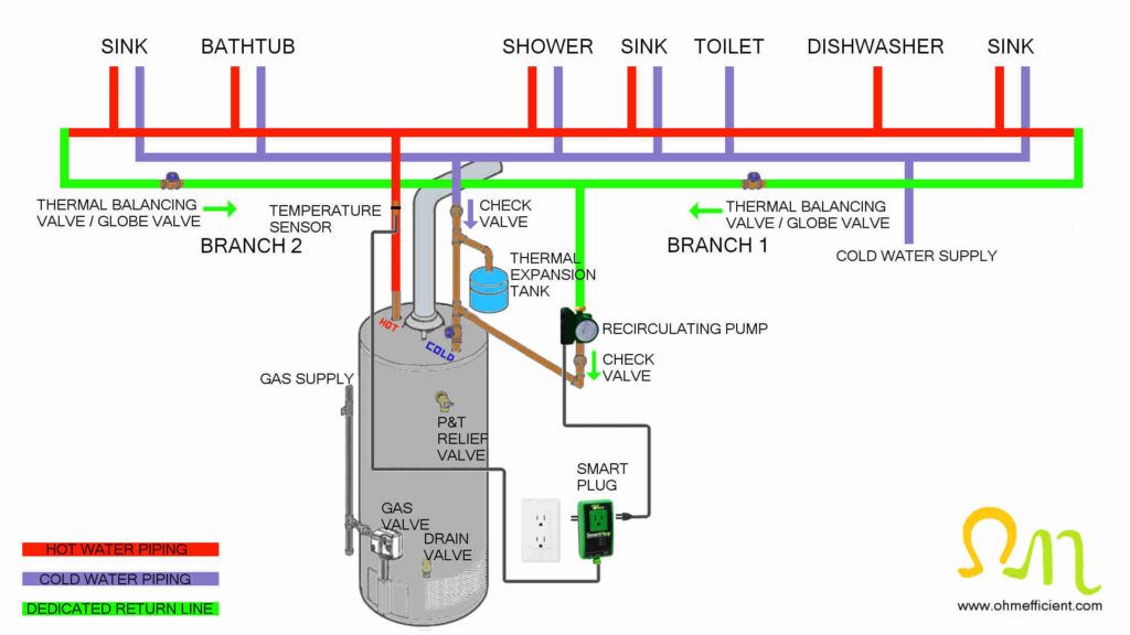
The second check valve installed above the thermal expansion tank on the water heater cold water supply also serves two purposes.
The flow switch alone is not able to detect when a faucet is closed and hot water is no longer required. The flow from the recirculating pump is more than enough to displace the permanent magnet within the flow switch. Therefore, when there is no longer a need for hot water, without an aquastat the recirculating pump would never turn off.
Each sprinkler & nozzle will push out water at different rates, but the key factor is the flow rate of your water supply. Work that out with a simple timed bucket test. From there, you can work out how much water each sprinkler you’re looking at uses & work within your flow limit. For more information, check our Product Guides.
Obtain the size of the water heater tank directly from the label on the water heater. Measure the city water supply pressure within the building using a water pressure gauge. Connect the water pressure gauge to either the washing machine or outdoor hose spigot connection. The thermal expansion tank pre-charge pressure should match the water pressure inside the building. Obtain the P&T relief valve setting directly from the label on the valve. The setting is generally around 150 PSI. The expansion tank calculator suggests that the initial temperature of the water within the water heater be entered into the calculator at 90oF. Setting the initial temperature to a lower value should only apply if the entire contents of the water heater are drained on each use. The final temperature of the water within the tank depends on your personal preference. Generally this setting is around 140oF.Once the calculator determines the thermal expansion volume, you need to select a thermal expansion tank that is larger than this value. For example, if the water volume from the calculator is 1.3 gallons, you would need to select the 2.1 gallon expansion tank. If the volume calculated was 2.3 gallons, you would therefore need to select the next size of expansion tank which is 4.5 gallons.
The recirculating pump for this installation generally incorporates a built in timer. The timer allows the homeowner to set when the pump can run based on their schedule. Most often, the timer is set to run the pump in the mornings and evenings for instant hot water during showers and dish washing. The timer can be set to the off position during the day when no one is home and there is no need for instant hot water. Timers on pumps can be inconvenient when instant hot water is desired, but not available if the timer is set to off. In this situation, the ambient temperature water within the hot water line would need to be flushed out before hot water is available.
Running a hot water recirculating pump 24 hours a day would be an example of an inefficient pump installation. Operating the pump in this fashion does guarantee hot water availability the instant a hot water faucet is opened. However, this installation increases the electricity consumption required to operate the pump. Natural gas consumption also increases because of the heat transfer losses from the hot water lines. The rate at which heat transfers in this example are at its highest, because of the maximum temperature difference between the water and ambient air. As a result, the water heater cycles on and off more often. This increases energy consumption as well as decreases the life expectancy of the water heater. Access to instant hot water with minimal energy consumption is achievable when a hot water recirculating pump operates efficiently.
There are two easy methods to determine the amount of water waste while waiting for the water to become hot. One method is to turn on a hot water faucet and time how long it takes to receive hot water. The other method is to calculate the volume of the hot water plumbing line to each individual faucet.
As the inside diameter of the pipe increases, the overall effect friction loss has on system head loss decreases. The increased amount of water within the cross sectional area of the pipe outweighs the increased surface area’s surface roughness.
Plumbing systems with demand recirculating pumps are the most efficient plumbing configurations for receiving instant hot water. Demand initiated recirculating pumps are the most efficient because hot water is only drawn into the recirculating loop when hot water is used. Note: Trunk and branch configurations with dedicated return lines can also increase efficiencies with demand initiated recirculating pumps.This recirculating system requires even more hardware in addition to the check valve and thermal expansion tank from method two. This system also requires an aquastat as well as a method to initiate the recirculating pump. Either a push button, motion sensor, or a flow switch can initiate and start the demand recirculating pump.
Globe valves can be used as a cheaper non-automatic alternative to thermal balancing valves. The flow rate of the water returning to the water heater is adjusted by changing the distance between the valves plug and seat. This distance changes the resistance the globe valve introduces into the system. Turning the globe valve closer to the closed position, shifts the system pressure drop to the valve which reduces the flow in the system.The globe valves on dedicated return line branches closer to the recirculating pump will need to be closed more than branches with greater distance. Once installed, all the globe valves throughout the system will need to be manually adjusted. Furthermore, additional adjustments may be required to receive hot water at every fixture throughout the building within a tolerable amount of time.
As you install a system, it’s almost inevitable that small fragments of dirt will get into the pipe, for this reason you should always flush out the system before running it the first time. This can be done by leaving an open end at the farthest point of each irrigation zone & operating the zone for 15 or so seconds to flush it out. Then plug it up & you’re good to go! This can also be said for any other times dirt may have gotten into the system (eg: further irrigation repairs or a mains water supply fault).
Placing the aquastat after the last fixture within the loop allows for the aquastat to turn off the recirculating pump earlier. This is the ideal location which provides hot water to all fixtures as well as minimizes the heat losses within the loop. If the distance from the last fixture to the water heater is large, reducing the amount of hot water within the loop increases system efficiency.
The total volume between the kitchen faucet and water heater is 0.54 gallons + 0.58 gallons = 1.12 gallonsWith the 2.2 GPM flow rate of the kitchen faucet, the additional water waste from mixing can be between 10 to 50% larger than the pipe volume.1.12 gallons * 110% = 1.23 gallons1.12 gallons * 150% = 1.68 gallons
In addition to the 90 feet of straight copper tubing, we also need to calculate the equivalent lengths of pipe for the six 90o elbows, two 45o elbows, flow switch and check valve. Table 14.7 of the Copper Tube Handbook has equivalent lengths in feet for common fittings. From this table, a nominal ¾ inch pipe 90o and 45o elbow have equivalent lengths of 2 and 0.5 feet respectively.Equivalent Length of Pipe = 90 ft + (6 x 2 ft) + (2 x 0.5 ft) + flow switchequivalent length + check valveequivalent length
A column of water 2.31 feet in height will have a gauge pressure at the bottom of 1 PSI. Therefore, 1 PSI of pressure drop in a system equals 2.31 head feet.
Aquastats are available with either a fixed or an adjustable temperature setting. Generally, settings for fixed temperature aquastats are 115oF/95oF. The contact within the aquastat is open at 115oF and then closes at a temperature of 95oF. This application requires the setting of the water heater temperature to be above 115oF. The temperature of the water needs to be hot enough to open the aquastat and turn off the recirculating pump.
If you are uncomfortable or do not completely understand the equipment or how to wire it, it is best to hire a professional for help. Follow electrical safety rules to prevent death, serious injury and equipment/property damage. Adhere to local electrical codes while wiring the recirculating pump junction box.
These brass fixed pressure regulating valves are ideal for systems which require reduced & regulated pressure, like drip irrigation systems. For areas with high pressure.
When hot water heaters are centrally located in a trunk and branch plumbing configurations, the dedicated return line can be connected to multiple branches to recirculate water. The dedicated return line connecting to each branch additionally requires a thermal balancing valve. The thermal balancing valves control the flow of water returning through the dedicated return lines based on a temperature setting. Without thermal balancing valves, branches closer to the recirculating pump will receive hot water faster than branches with further distance. The addition of thermal balancing valves in this application ensures instant hot water is available at all fixtures throughout the system.
Structured plumbing is an energy efficient plumbing configuration which reduces both water waste and the amount of energy required to provide hot water. Several design requirements need to be implemented in order for a plumbing configuration to be classified as “structured.”Structured configurations utilize a hot water recirculating loop generally of ¾-inch diameter with individual twigs connecting to each hot water fixture. The piping for each twig should not exceed ½-inch diameter. Additionally, the length of pipe for each twig connecting a fixture to the hot water circulation loop should not exceed 10 feet (3m). Limiting the pipe length and diameter of each twig reduces the amount of ambient temperature water sitting within the twig to 0.5 liters (2 cups). This is the amount of water that will flow through the faucet, shower, or appliance before hot water reaches the fixture.Install the hot water recirculating loop in a way to minimize the overall length of pipe necessary while maintaining the 10 foot twig length requirements. Additionally, use the smallest practical pipe diameter for the recirculating loop while still maintaining system pressure and velocity requirements.There are several advantages to reducing the recirculating loop pipe diameter. First, smaller diameter piping decreases the volume of water within the recirculating loop. Second, reducing the amount of ambient temperature water returning to the water heater reduces the energy required to reheat the loop. Additionally, heat losses increase with the diameter of the pipe, the length of the recirculating loop, and inversely with the speed at which the water moves within the loop.
Truck and branch plumbing configurations resemble characteristics of a tree. The trunk is a larger diameter line that connects to the water heater and generally runs across the house. The larger diameter pipe ensures adequate water flow when multiple faucets are open at the same time. Branches are usually smaller diameter lines that connect various areas of a house like the kitchen or bathroom for example to the trunk. Lastly, twigs make the final connection from the branch to an individual faucet or appliance.The trunk and branch plumbing system configuration is best suited for smaller homes with centralized faucets and appliances. Implementing a trunk and branch configuration in larger homes with non-centralized faucets and appliances, results in the plumbing system becoming highly inefficient. The volume of water within the plumbing lines is significantly larger and results in prolonged waiting times and excessive water waste. Therefore, trunk and branch plumbing configurations need to limit pipe length to minimize inefficiencies.
At high flow rates (4-6 GPM), hot water pushes the ambient water out of the line quickly. As a result, the least amount of mixing occurs. Bathtubs and laundry sinks with no aerators are examples of faucets that typically have these high flow rates. The amount of water exiting faucets at higher flow rates will typically be less than 110% of the volume of the line before the water becomes hot. More mixing occurs, as the rate of flow decreases (1-3 GPM) to a range common for sinks and shower heads. The volume of water exiting these faucets is 10-50% more than the volume of the line. At low flow rates (< 1 GPM), an interesting form of mixing occurs. A thin layer of hot water travels on top of the ambient temperature water around the perimeter of the pipe. This thin layer travels a significant distance down the pipe before a more normal form of mixing occurs. Due to this unique mixing, the amount of water exiting low flow faucets can be twice the volume of the line before the water becomes hot.
The projected flow rate from the water demand calculator is 9 GPM. The velocity of the water moving through the ½-inch pipe is more than two times faster than the ¾-inch pipe.Velocity of water flowing at 9 GPM through a ½-inch copper line:
Push buttons are usually located near faucets within bathrooms. Momentarily pushing the button, starts the recirculating pump and provides instant hot water upon opening the faucet. The drawback with a push button, is that you will most likely have to educate guests on its purpose. Otherwise, guests may not know what the button is for, and will most likely pour water down the drain while waiting for hot water.
A hot water recirculating loop consists of 90 feet of ¾-inch type M copper tubing as well as 6 – 90o elbows, 2 – 45o elbows, a flow switch and a check valve. Calculate the head loss of the system at 10 GPM.The first step is to calculate the velocity at which the water travels within the ¾-inch type M copper pipe at 10 GPM. ¾ inch type M copper pipe has a 0.811 inch inside diameter. To keep the units of measure constant throughout each equation, we convert GPM to ft3/s and inches to feet.
The next step is to solve for the Haaland friction factor equation which takes into account the relative roughness and internal to viscous forces.
After calculating the GPM operating point of the system, you can then determine the amount of time it takes to recirculate water through the loop.The volume of water within the 90 feet of ¾ inch type M copper recirculating loop is 2.42 gallons.
The Taco smart plug and temperature sensor kit also comes with a sensor valve that incorporates a removable cartridge for servicing.
This article describes how to receive instant hot water at all hot water faucets, showers and appliances within a building. No longer having to wait for hot water reduces water waste as well as lowers water utility bills. Installing a recirculation pump within the plumbing system is the only way to receive instant hot water at every faucet. This article also reviews the three most common recirculating pump installations and outlines the pros and cons of each installation.
Hot water recirculating pumps decrease the time it takes to receive hot water, which as a result reduces water waste. The pump system creates a loop, which pulls hot water from the water heater and returns the ambient temperature water sitting within the hot water lines. The ambient temperature water is then re-heated, rather than being poured down the drain. Additionally, this system ensures that hot water is instantly available upon opening a hot water faucet.
When water is heated, it expands in volume by as much as 3 to 4%, depending on the initial and final temperatures. Since water is not compressible, thermal expansion increases the pressure within the water heater when there is no place for this pressure to be displaced. In “open water” systems, systems without check valves or backflow preventers, this pressure dissipates into the city’s cold water supply.When a check valve is installed on the cold water supply of a water heater, a thermal expansion tank is required. The check valve isolates the water heater from the city’s cold water supply which creates a “closed water” system. Without a thermal expansion tank, the pressures within the water heater and the system piping can reach dangerous levels. The pressures would rise above the safety setting of the pressure and temperature relief valve during each heating recovery cycle where hot water is not drawn. The relief valve will eventually fail after too many operations, which can result in the failure of the water heater.Installing an expansion tank between the water heater and the cold water supply check valve provides a place to dissipate this thermal expansion. When a hot water faucet is open, the pre-charged pressure within the expansion tank prevents water from entering the expansion tank. When the hot water faucet is closed the water heater continues to heat the water within the tank during the recovery cycle. During the recovery cycle, the expansion tanks pressurized air cushion compresses and makes room for the additional expanded water volume. This provides a space to store the additional water, which prevents excessive system pressure buildup. When a hot water faucet is opened again, the compressed air cushion within the expansion tank forces the water out and back into the water heater.
Plastic pressure reducers can’t handle constant high pressure so the benefit with a brass pressure regulator is that you can put one on at the water connection for a drip irrigation system rather than one plastic pressure reducer on each zone.
Taco has made an alternative to the timer based recirculating pump with sensor valves. Rather than using a timer directly on the pump itself, Taco has a smart plug and temperature sensor kit. The smart plug controls and supplies power to the recirculating pump. Additionally, a temperature sensor installs on the hot water piping a minimum of 18 inches away from the water heater. This temperature sensor then connects directly to the smart plug. The smart plug uses the information from the temperature sensor to determine hot water use within the home. Based on this information, the smart plug will automatically turn on the recirculating pump when required. The smart plug continues to monitor hot water demands, therefore if demands change, the smart plug automatic schedule adapts. This is convenient in comparison to the timer based pumps. For example, demands for instant hot water typically change from weekdays to weekends.
When hot water heaters are centrally located in a trunk and branch plumbing configuration, use multiple sensor valves to recirculate the water. Depending on the size and length of branch #2, the sink and bathtub may not receive instant hot water if only branch #1 had a sensor valve. Installing an additional sensor valve beneath the sink on branch #2 ensures instant hot water is available at all fixtures throughout the system.
Plumbing systems with a dedicated return line can receive instant hot water by installing a recirculating pump within the return line. A dedicated return line can also be added to traditional trunk and branch systems in buildings with easy access (unfinished basements etc.). The recirculating pump needs to be installed with the direction of flow pointing towards the water heater. Additional hardware such as check valves and an expansion tank are required for this recirculating system to operate efficiently.
There are online calculators available that properly size expansion tanks. These calculators require specific information which includes the following:

Luckily the replacement unit was the same length as the old 2 to 1 reducer. So replacement was effected in 15 minutes. The new 500kPa pressure reducer exhibits a higher flow rate characteristic relative to the replaced unit. Supply and postage was prompt.
We definitely don’t recommend it. Typically, drip tube will deliver the water at a far slower rate that sprays. Because of this, if you were to have both on the same zone, the areas with drip would be left far drier than the areas with sprinkler coverage. If you do want to water some areas with drip & some with sprinklers, it can be done, but each will just need to be run on their own separate irrigation zones.
Hot water stored in plumbing pipes will eventually cool to ambient temperatures. The heat from the water transfers through the pipes and absorbs into surrounding objects. To receive hot water at a faucet, this ambient temperature water first has to flow out of the line. Generally, this water pours down the drain, as we wait for the water to become hot. The amount of water poured down the drain depends on the length and diameter of the pipe between the faucet and water heater. The rate at which water flows through the line also affects the amount of water that goes down the drain before hot water reaches the faucet.The diameter and the length of the pipe determines the volume of ambient temperature water stored within the plumbing line. The flow rate of the water exiting a faucet determines how the hot water mixes with the ambient water within the line. Ideally, the least amount of water waste would occur if the hot water and ambient water did not mix. Unfortunately, these waters do mix and the way they mix changes depending on the flow rate of the water.
There’s no best type of sprinkler, just better sprinklers for different applications. Gear Drives are better for large areas, over 5m. Pop-Ups are ideal for 1.5-5m & Micro sprays are excellent for anything under that.
Drip tube is excellent in areas of rich dense soil where water spreads nicely throughout. Installed under mulch, the water is delivered with minimal evaporation & wastage, going direct to the root ball.
It takes 38 seconds for hot water to reach a faucet that has a flow rate of 2.2 GPM. How much water flows through the faucet during this period?
\small h=f\cdot \frac { L }{ D } \cdot \frac { { V }^{ 2 } }{ 2g } \\ \begin{alignedat}{5}f&:friction\; factor &=&\; 0.021946\\ L&:equiv.\; length\; of\; pipe\; &=&\; 124ft\\ D&:pipe\; inside\; diameter\; &=&\; 0.06758ft \\ V&:velocity\; &=&\; 6.21083{ ft }/{ s } \\ g&:gravity&=&\; 32.2lbm{ ft }/{ { s }^{ 2 } } \end{alignedat}
The Reynolds number (Re) is a dimensionless number comprised of the physical characteristics of flow. This calculation is also nested inside the Haaland friction factor equation. The Reynolds number is a ratio of internal forces (fluid speed) to the viscous forces. The value of the Reynolds number predicts if the flow conditions will be either laminar or turbulent. If the viscous forces are larger, the Reynolds number will be smaller and the flow regime will then be laminar. When the fluid speed is larger, the Reynolds number will be larger and the flow regime will then be turbulent. An increasing Reynolds number indicates an increasing turbulence of flow.The viscosity and density of water changes with temperature. The cooler the water, the higher the viscosity and density values. Higher viscosity and density values also result in an increase in head loss. Room temperature is the coolest the water within recirculating loop will become. For this example, room temperature will be 70oF.
\small \begin{alignedat}{2}h&=0.02194\cdot \frac { 124ft }{ 0.06758ft } \cdot \frac { { \left( 6.21083{ ft }/{ s } \right) }^{ 2 } }{ 2\cdot 32.2lbm{ ft }/{ { s }^{ 2 } } } \\ h&= \fcolorbox{black}{yellow}{24.1ft} \end{alignedat}
You may need to recalculate the equivalent lengths of pipe for the flow switch and check valve to verify that the equivalent length at 10 GPM does not change at the operating point of 10.5 GPM.
Flow switches are manufactured for various applications that require different GPM flow rate settings. These different flow settings are achieved by redirecting water around the permanent magnet which actuates the reed switch when displaced. Flow switches with built in bypass ports of various sizes require higher GPM flow rates to displace the permanent magnet. Therefore, selecting a flow switch with a flow setting lower that the lowest GPM faucet within the building is important for this system to function properly. The stainless steel spring within the flow switch returns the permanent magnet when the flow through the switch decreases.
Placing a strainer on the cold water supply to the building is recommended when using thermal balancing valves. The strainer prevents debris from entering the thermal balancing valves modulating cartridge which as a result, prolongs the life of the valve.
Buildings with traditional truck and branch plumbing configurations can receive instant hot water by installing a recirculating pump and sensor valve. The recirculating pump connects directly to the hot side of the water heater. The sensor valve connects between a sink faucet and both the hot and cold water supplies. Place the sensor valve beneath the sink furthest from the hot water heater. Locating the sensor valve at the sink furthest from the water heater, allows all fixtures in between to receive instant hot water.
The last step would be to calculate the total system head loss using the Darcy head loss equation. We know all the values within the equation with the exception of the equivalent length of pipe. The equivalent length of the piping system is the length of all straight pipe segments plus the equivalent lengths of other components such as fittings and valves. In theory the pressure drop through the fitting is equivalent to the pressure lost through a certain length of pipe at that corresponding flow rate.
When hot water is not in use, these check valves need to be in the closed position to ensure overall system efficiency. The check valves for this application therefore, need to be of the spring loaded type which are closed by default.
Relative roughness is the surface roughness in relation to the piping materials inside diameter. The relative roughness calculation is nested inside the Haaland friction factor equation. A piping material’s surface roughness (Ɛ), develops a friction loss as water contacts the pipe walls while flowing through it. The two most commonly used domestic water piping materials are copper and PEX. The surface roughness of these materials are between 0.0013-0.0015mm and 0.0005-0.0007mm respectively. Additionally, the degree in which these friction losses affect system head losses varies with the inside diameter of the pipe. To keep the units of measure constant throughout each equation, we convert mm to ft.
Flow switches in this application detect the presence of hot water flowing from the water heater upon opening a hot water faucet. When enough water is flowing through the flow switch, an internal normally open reed switch closes. This contact along with an auxiliary relay can then supply power to the recirculating pump.
Calculating the volume of the plumbing line, correspondingly determines the amount of water within the line between the faucet and the water heater. Additionally, the flow rate of the water within the line determines the amount of water waste while waiting for the water to become hot. To calculate this, simply multiply the volume of the line by 110% for 4-6 GPM flow rates, 110-150% for 1-3 GPM flow rates and 200% for flow rates less than 1 GPM.
\small \begin{alignedat}{2} density\; 70℉&=62.3{ lbm }/{ { ft }^{ 3 } }\\ viscosity\; 70℉&=0.00065442{ lbm }/{ ft.s } \end{alignedat}
Thermal balancing valves automatically balance recirculating loops in domestic hot water systems. They ensure the speed of hot water delivery to every branch within the plumbing configuration. The valves automatically modulate the flow of the water returning through the dedicated return lines back to the water heater. This is accomplished by adjusting the temperature setting on the thermal balancing valve. A thermal element within the valve cartridge opens and closes the valve depending on the temperature. As the temperature of the water flowing through the valve increases the valve gradually closes to a minimum value. The valve does not completely close, as a minimum flow is required for the valve to monitor the temperature of the water flowing through it. As the temperature decreases the valve gradually opens, allowing more flow to maintain the set temperature.Placing these valves on each dedicated return line from various branches allows for the recirculating system to provide instant how water to all fixtures within a building. The thermal balancing valves on the branches closest to the recirculating pump will close to the minimum setting first. This allows the recirculating pump to supply water to further branches faster.
Structured plumbing requires the hot water recirculating loop to return to the water heater after connecting to the last fixture. A demand style recirculating pump installs in the return loop before the loop reconnects to the water heater. If the water heater has a dedicated return line connection, the recirculating pump and return line can connect to this fitting. If a dedicated return line connection does not exist, the return loop can connect to the cold water supply of the water heater.Return loops can also connect at the bottom between the tank and the drain valve. Connecting the return loop in this location works, however, it is not a requirement. The cold water supply connection of hot water tanks incorporate a dip tube within the tank. The dip tube takes incoming cold water to the bottom of the tank where it is then heated. Therefore, connecting the return loop to the cold water supply or drain valve is functionally the same connection.
The Taco smart plug and temperature sensor kit comes with a recirculating pump that incorporates an ECM motor. An electronic commutated motor is a higher efficiency permanent magnet motor that reduces the total electricity consumption of the system. Decreasing the electricity consumption, increases the overall efficiency of the system for providing instant hot water.
Upon activating the system (push button / motion sensor / flow switch) the pump returns the cooled water within the loop back to the water heater and fills the loop with hot water. When the water within the loop reaches the temperature setting of the aquastat, the recirculating pump turns off. The pump only runs when there is a real time demand for hot water and when the water in the recirculating loop has fallen below the aquastat temperature. This sequence of operation minimizes the recirculating of hot water and accurately matches hot water delivery to hot water usage. Recirculating hot water based on water usage reduces the overall heat losses from the plumbing system which increases efficiency.
The temperature difference of 20oF between the high and low settings for these fixed temperature aquastats may be an issue. The water within the recirculating loop needs to drop to 95oF before the recirculating pump can turn on. If you desire instant access to a minimum hot water temperature of 105oF, then you will require an adjustable temperature aquastat.The high and low temperature settings for adjustable aquastats can be set to your liking. Typically, they still require a minimum temperature difference of 10oF between the high and low settings. For example, the high setting can remain at 115oF and while increasing the low setting to 105oF. Adjustable aquastats therefore allow for tighter control of recirculating pump operation.
A combination of measurements and calculations determine the head loss for the system. Additionally, the results from these calculations change depending on the volumetric flow rate. Since these results need to be calculated multiple times at different flow rates, it is best to use a spreadsheet to save time. It is also important to keep the system of measurement consistent throughout the calculations. We will use the imperial system in the following example.The following equations determine system head loss:
These brass fixed pressure regulating valves are ideal for systems which require reduced & regulated pressure, like drip irrigation systems. For areas with high pressure.
Using motion sensors as an alternative to using a push button can also start the demand initiated recirculating pump. Starting the pump with motion sensors eliminates the need to educate guests about the system. The drawback with motion sensors is that there are many times when a bathroom is in use without the need for hot water. Simply walking into the bathroom to check your hair for example, would start the recirculating pump. This would be a waste of energy as the hot water within the loop would eventually cool to ambient temperatures.
The reed switch within the flow switch assembly is not capable of handling the current draw of the recirculating pump. The reed switch therefore, needs to be wired to a single pole normally open auxiliary relay capable of switching the current draw of the recirculating pump. Additionally, this application requires RC protection of the reed switch contact. The reed switch RC protection is required because the reed switch electrical current ratings are for resistive loads. Auxiliary relay coils are inductive loads that generate a high frequency voltage when the current flowing through the coil is interrupted. Without RC protection, this high frequency voltage arcs across the reed switch contacts which can weld the contacts together as a result. The RC protection prevents arcing by providing an alternative path for this high frequency voltage.Under normal operating frequency 50/60 Hz, the high capacitive reactance within the RLC circuit results in high impedance, resembling an open circuit. When the current through the auxiliary relay coil is interrupted, the frequency increases, which decreasing the capacitive reactance value of the RLC circuit. When the capacitive reactance value decreases, the impedance decreases, providing an alternate path which protects the reed switch contacts.Refer to the wiring diagrams below.
Repeat this equivalent length calculation with information provided from the check valve manufacturer.Equivalent Length of Pipe = 90 ft + (6 x 2 ft) + (2 x 0.5 ft) + 11 ft + 10 ftEquivalent Length of Pipe = 124 ftNow that all the values for the Darcy head loss equation are known, the total system head loss at 10 GPM can be calculated.
\small \begin{alignedat}{2}f&={ \left( \frac { 1 }{ -1.8\log _{ 10 }{ \left[ { \left( \frac { { { 4.265\Epsilon }^{ -6 } }/{ 0.06758ft } }{ 3.7 } \right) }^{ 1.11 }+\frac { 6.9 }{ 39960 } \right] } } \right) }^{ 2 } \\f&=\fcolorbox{black}{yellow}{0.021946} \end{alignedat}
From the pressure drop and flow rate graph, the manufacturer of the flow switch indicates a 1 PSI drop in pressure at a 10 GPM flow rate.
The way a plumbing system is configured within a home determines how a hot water recirculating pump can be installed. A majority of buildings across North America have either a truck and branch or a manifold (aka home run) plumbing configuration. Structured plumbing is another configuration that has recently gained popularity with energy efficient home builders.
Determining water waste using the timing method is surprisingly easy. Simply start a timer once the hot water faucet opens and stop the timer once the water becomes hot. Knowing the flow rate of the faucet is important for this method to be accurate. Many faucets have flow rate engravings directly on the nozzle, usually on or near the aerator screw on tip. Flow rate engravings are usually in this area because aerator’s mix air into the water, which reduces the rate at which water exits the faucet.Bathroom faucets typically have aerators that reduce the flow rate between 0.5 and 1.5 GPM. Kitchen faucets generally have a flow rate of 2.2 GPM. Some faucets may not have a flow rate engraving or indication anywhere. Determine the flow rate of these faucets by either referring to the manual or by measuring the flow rate. To measure the flow rate, take a large water pitcher and measure how much water flows in one minute. Simultaneously pausing the timer and closing the faucet may be necessary a few times, if the pitcher/bag becomes full.Once you know the flow rate of the faucet, determining water waste is simple. Simply multiply the flow rate by the amount of time it takes to receive hot water.
You need to calculate system head losses at varying flow rates to properly size demand initiated recirculating pumps. These calculations will then produce a system curve. The system curve represents the pump head required to move water through the recirculating loop at various flow rates. Increasing the recirculating loop flow rate increases the system head losses exponentially. The pump curve provided by the manufacture represents the pump’s ability to produce flow against system head losses. Together, the system curve and pump curve determine the operating flow rate of the system. The operating flow rate of the system is the point at which these two curves intersect.
With Irrigation, Garden Lighting, Pond Pumps & Filtration, Pressure Pumps & Water Tanks, Turf & More available to buy online at our store, SunshowerOnline is the place to go to bring your garden to life! Located in the South East suburbs of Melbourne, Victoria, we have decades of experience to give you the information and advice you need to make your garden award worthy! Have a browse through our Product Categories, Shop by Brand, check out our great Specials, get handy advice from our Help Centre & Blog, then buy online with just a few clicks!

Using a common equivalent length value that accounts for friction losses through fittings such as elbows and tee connections is reasonably accurate. Using a common equivalent length value for components such as valves, sensors, and switches can introduce significant error. The reason for this source of error is that different manufacturers have varying designs for the same component. The way water changes direction and velocity as it flows through a component, determines the pressure drop across the component. Referring to the manufacturer’s specification sheet, the pressure drop for the desired flow rate can be converted into an equivalent length of pipe. The equivalent length of the component, then adds to the overall system equivalent length, which then produces the system curve.
Thermal expansion tanks come from the factory with a pre-charge that is typically around 20 PSI. Before installation, increase the pre-charge to the same pressure as the city’s water supply pressure measured within the building. Use a simple bicycle pump to increase the pre-charge pressure within the thermal expansion tank. Verify the pre-charge pressure using an air pressure gauge to be sure the pre-charge pressure is the same as the water supply pressure.The pre-charge pressure within the thermal expansion tanks should be tested annually to ensure no pressure has been lost. To test this, simply close the main water supply valve near the water meter and open a faucet within the building. This relieves the pressure off of the top of the expansion tank diaphragm. Then, simply measure the pre-charge using the air pressure gauge and adjust as needed.
For new installations or renovations, it’s important to determine the system pressure and velocity requirements before selecting pipe size. Domestic water systems require a minimum pressure to ensure that all fixtures have proper quantities of flow. Limiting the speed at which water flows within the pipes is important to prevent excessive noise and corrosion. Higher velocities, increase the rate of corrosion which can then lead to pipe failure. Velocities should not exceed 10 feet per second and should be designed for 7-8 feet per second or less.
Filling the entire recirculating loop with hot water would take 13.8 seconds. The first fixture within the recirculating loop would receive hot water instantly. If all the fixtures are located within the first half of the loop, then all fixtures would receive hot water within 6.9 seconds. When fixtures are located near the end of a lengthy recirculating loop, the wait time for hot water can still be long. In this example, the wait time would be approximately 14 seconds. Note: Systems with longer recirculating loops could experience longer wait times.Using a combination of initiating devices can solve this problem. For example, use a push button in conjunction with the flow switch to start the recirculating pump before using these fixtures. If the fixtures belong to an ensuite bathroom, the homeowner would have the understanding of the button’s function, without having to educate guests.
The diameter of the plumbing line (½-inch or ¾-inch etc.) and the length of the plumbing line between the water heater and faucet determines the volume of water within the line. The formula for calculating the volume of a cylinder correspondingly calculates the amount of water within a plumbing line.
Fittings such as tee’s, elbows, reducers, valves, etc. change the course of motion the water takes while flowing through piping. The turbulence created when redirecting the water creates additional friction losses. Minimizing the amount of fittings with good system design and replacing sharp 90o elbows with larger gentle bends reduces these friction losses.
Installing a flow switch within the plumbing system near the water heater is the best solution for demand recirculating pumps. There is no button to press and therefore no educational requirements for guests as well as no motion sensor inadvertently starting the recirculating pump. The flow switch simply senses hot water flow upon the opening of a hot water fixture. After sensing flow, the flow switch turns on the demand initiated recirculating pump which then quickly supplies the loop with hot water.
Check valves rely on pressure differential to work. They require a higher pressure on the input side of the valve than the output side to open the valve. When the pressure is higher on the outlet side or the input side pressure is not high enough, the valve will close.Two check valves are required for this setup. One check valve installs between the recirculating pump and water heater on the dedicated return line. This check valve serves two purposes:
The last requirement for structured plumbing is that the recirculating loop piping and twig connections need to be insulated with a minimum of R4 pipe insulation. To accommodate the pipe insulation, use pipe hangers to lower the recirculating loop from the floor joists. The insulation ensures that the water temperature within the recirculating loop remains hot for thirty to forty five minutes from the last time hot water was used. This increases the efficiency of the system when hot water is used multiple times within a short period.
Recalculate the system head losses at varying flow rates to produce the following graph. Then plot the recirculating pump curve information provided by the manufacturer onto the graph. The point where these two curves intersect is the expected operating point of the system.
A check valve and a properly sized thermal expansion tank will keep the plumbing system pressure below the safety P&T relief valve setting. Size the expansion tank to a volume that is larger than the expanded volume of water caused by heating. Calculating the change in volume of water from a lower temperature to a higher temperature can be difficult. The reason for this is that water’s volumetric temperature expansion coefficient changes with the temperature of the water.
Installing a hot water recirculating pump will reduce water waste; however, the pump as well as the plumbing system as a whole must operate efficiently to minimize energy consumption. Installing a hot water recirculating pump without efficiency in mind, can increase electricity as well as natural gas consumption.
The sensor valve is the integral component for providing instant hot water for this system. It is required when a third dedicated return line does not exist or is cost prohibitive to install. Rather than using a dedicated return line to the water heater, the sensor valve uses the cold water line to recirculate the water instead.The sensor valve operates as a thermostatically controlled bypass valve. A temperature sensitive actuator is located in between the hot and cold supply ports within the sensor valve. When the temperature of the hot water line falls below approximately 90oF, the actuator closes. When the actuator closes, a passage “bypass” opens. The lukewarm water from the hot water line, then crosses over to the cold water line and flows back to the water heater for reheating.The recirculating pump quickly raises the temperature within the hot water line to the temperature of the hot water heater. The actuator within the sensor valve then opens at approximately 100oF. This closes the crossover passage between the hot and cold water lines. At this point, any fixture between the water heater and the sensor valve has access to instant hot water. This process repeats itself as heat radiates from the hot water line and the temperature of the water drops to 90oF.
Plastic pressure reducers can’t handle constant high pressure so the benefit with a brass pressure regulator is that you can put one on at the water connection for a drip irrigation system rather than one plastic pressure reducer on each zone.
No, drip tube isn’t simply holes punched into poly pipe. Inside each hole is an intricate dripper which delivers that water nice and evenly. Punching a hole will simply create an uncontrolled leak!
Need more help with Pressure Reducers & Filters, Pressure Regulating Valves ? Check out these handy resources from our Help Centre
The water meter within your home may be geared or is possibly setup in a way that does not measure reverse water flow exiting the house. In open water systems, each time the water heater completes a heat recovery cycle, thermal expansion pushes the expanded volume back into the city’s cold water supply. The next time you use hot water, this same water, then flows back into the house through the water meter. To put it another way, this means that you may be paying for this expanded volume of water twice. The additional benefit of installing a check valve and a thermal expansion tank is that it prevents this possibility.
Domestic water systems with pressures up to 50 PSI are generally designed with velocity limits dictating the pipe size. Systems with pressures below 35 PSI are generally designed around friction loss to reduce the amount of additional pressure loss.When sizing pipe diameters, the water demand for a building needs to be determined. The water demand is the projected flow rate based on the number of fixtures, the fixture flow rate as well as the probability of use. Online water demand calculators assist with determining the projected flow rate. Determining a buildings water demand is important because as water demand increases, both the velocity and friction losses increase as well.You can limit the velocity of the water traveling through pipes by increasing the pipe diameter. Insert the projected flow rate from the water demand calculation into the velocity equation to determine the velocity. Increase the pipe diameter until the equation results in a velocity of 7-8 feet per second or less. This will ensure system velocity requirements are met.
The total distance between the water heater and a kitchen faucet that has a flow rate of 2.2 GPM is 64 feet. The first 20 feet of plumbing line is ¾-inch type M copper tubing which then reduces to ½-inch type M copper tubing for the remaining 44 feet. The volume of water within the ¾-inch and ½-inch plumbing line sizes can be calculated individually then simply added together for the total volume.
\small V=\pi { r }^{ 2 }h \\ \begin{alignedat}{2}r&=radius\; of\; the\; plumbing\; line \\ h&=length\; of\; the\; plumbing\; line\end{alignedat}
The manifold or home run plumbing configuration has a direct connection between the manifold and the end device (faucet, shower, or appliance). The cold water supply connects directly to a cold water manifold. The hot water exiting the water heater connects directly into a hot water manifold located near the water heater. An individual hot and cold run, then connects from the each manifold to each individual faucet, shower, or appliance. This connection typically uses a smaller diameter flexible pipe such as PEX. Since each connection is direct, there are no additional fittings (elbows, tee, or couplings) required.There are several advantages to the home run configuration over the traditional trunk and branch configuration.
Plumbing lines made from different materials (PEX, copper) have slightly different inside pipe diameters for the same nominal size of pipe. Refer to the table below for the inside diameter for each pipe material.
The main cause of blowout is pressure. Whether it’s poly fittings, PVC fittings or timers, whatever the component, if the pressure is too high for what it’s designed for, kaboom! Simply solve the problem with a pressure reducer & make it a brass one if it’s on your water supply.
Aquastats are temperature monitoring devices with an electrically rated contact that opens or closes depending on the water temperature. In this application, we use the aquastat to turn off the recirculating pump once the water within the loop reaches the high temperature setting. They also prevent the recirculating pump from turning on if the water within the loop is above the low temperature setting.
Set the time delay mode function to either E “off delay” or F “single shot”. To set the time to 15 seconds, set the time interval to 1 minute and the percentage dial to 25%.
\small \begin{alignedat}{2}Re&={ \frac { 62.3{ lbm }/{ { ft }^{ 3 } }\cdot 6.2108{ ft }/{ s\cdot }0.06758ft }{ 0.00065442{ lbm }/{ ft.s } } } \\Re&=\fcolorbox{black}{yellow}{39960} \end{alignedat}


 8615510865705
 8615510865705